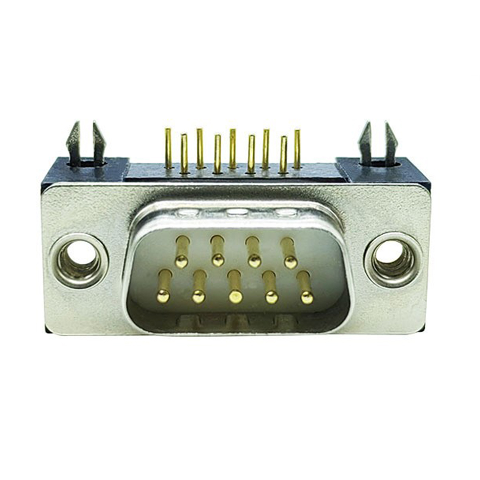
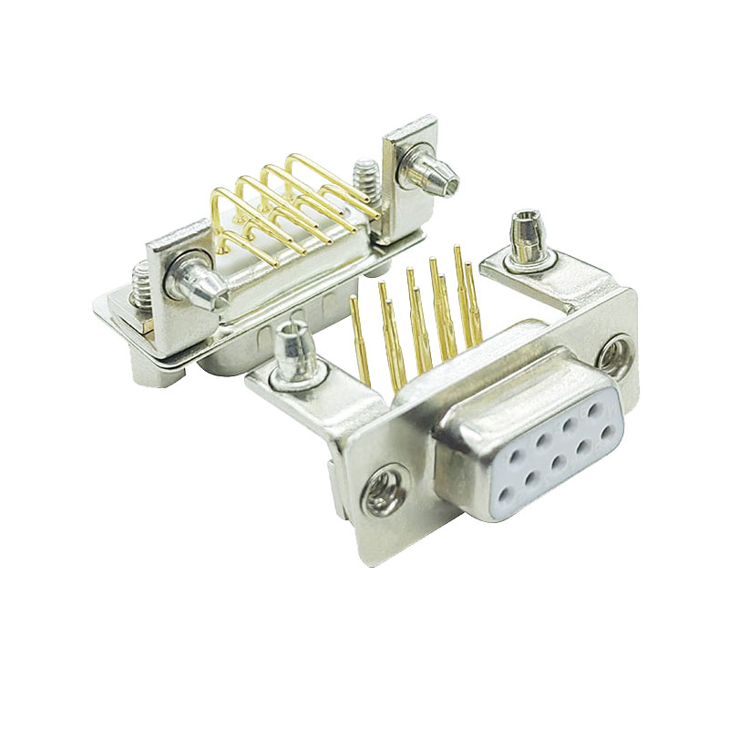
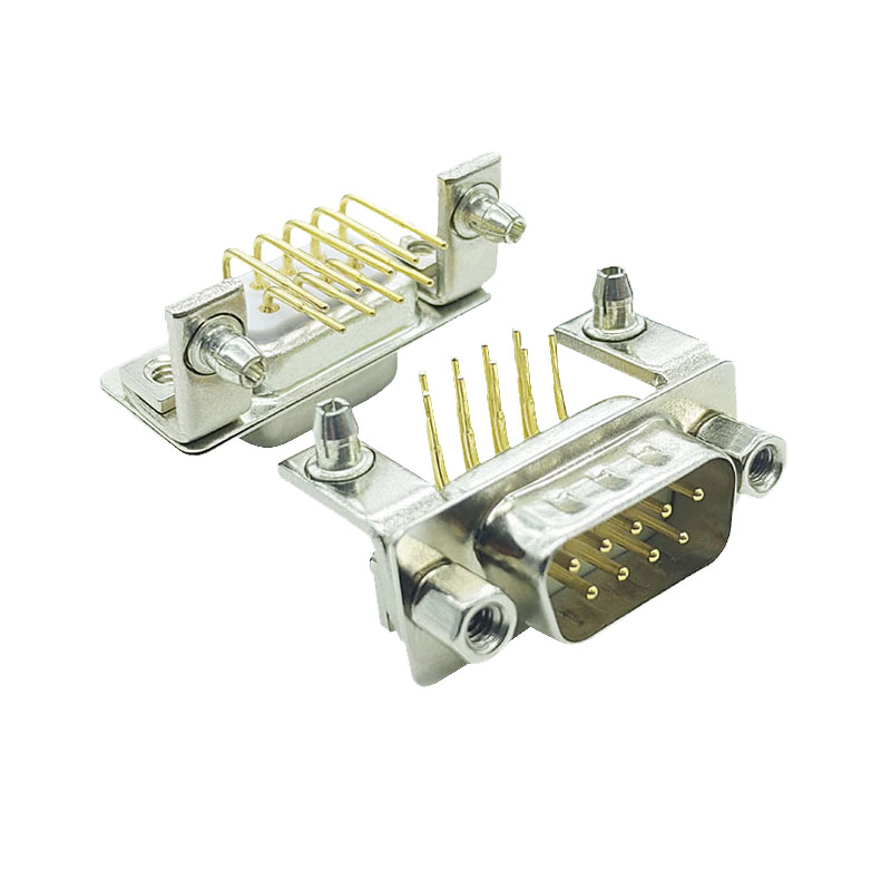
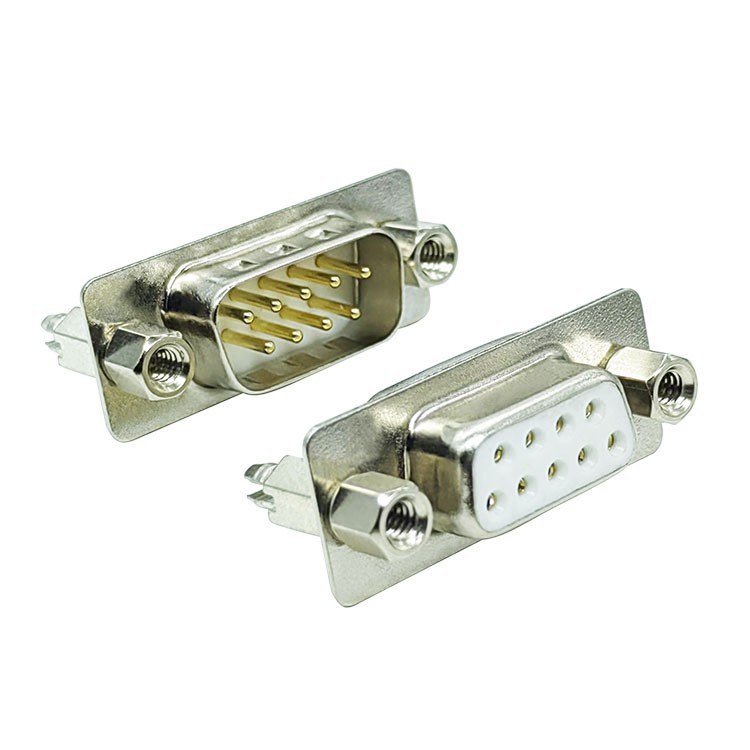
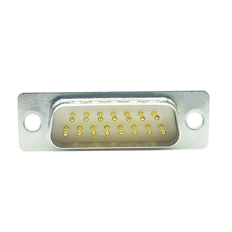
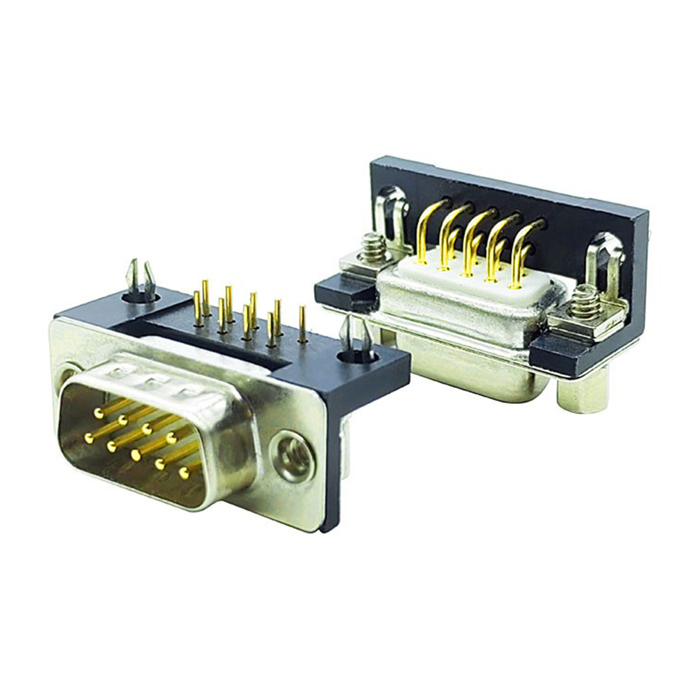
The 9-pin D-Sub connector, commonly referred to as "DB9" (the most accurate industry standard name is DE-9), is arguably the most famous and widely used member of the D-Sub family.
It is not only the classical physical interface of the RS-232 serial communication standard, but also the bridge between computers and various peripherals in the past decades.
Classic physical specifications
The 9-pin D-Sub connector is the smallest shell size E in the D-Sub family. It has an iconic trapezoidal metal shield enclosure and contains two rows of a total of nine signal pins (5 in the top and 4 in the bottom).
Anti-slip design: The unique "D" shaped metal casing can force anti-insertion through physical shape to ensure the accuracy of the connection.
Secure connection: The interface is usually fitted with standard screw holes on both sides, which can be effectively prevented from unexpected loosening in a vibration environment by screw tightening.
Male and female: divided into male with metal pins (Plug / Male) and female with pinholes (Socket / Female).
Core Electrical Performance
Despite its small size, the 9-pin D-Sub connectors are electrically reliable and can be adapted to a variety of harsh industrial environments:
Frontal and fixed current: The standard signal pin frontal and fixed current is usually 5A, which can carry a strong signal transmission.
Frontal voltage: Depending on the specific model and standard, the frontal voltage is usually between 250 V and 400 V.
Wide-temperature operating: With excellent environmental adaptability, standard industrial-grade products typically operate at temperatures between -55 ° C and 105 ° C (or 125 ° C) to meet the demands of extremely cold or high temperature environments.
Electromagnetic shielding: the metal shell can provide good electromagnetic interference (EMI) shielding effect, protect the internal sensitive signal from external noise.
Pin definition and RS-232 protocol
In the most common RS-232 serial communication applications, the nine pins of the 9-pin D-Sub connector have a clear division of labor. Although in actual simple communication, it is often only necessary to have 3 lines to achieve basic data interoperability, the full protocol is defined as follows:
Socket number Signal name Function description
1 DCD carrier detection (data ready)
2 RXD Receive Data (Core Signal Line)
3TXD Transmit Data (Core Signal Line)
4DTR Data Terminal Ready
5 GND signal ground (reference level reference)
6 DSR Data Device Ready
7 RTS request sent (for hardware flow control)
8 CTS clear send (for hardware flow control)
9-day ringing indication
Utility Tip: When connecting a microcontroller, debugging a industrial control device, or connecting an older serial port device, usually only need to connect the 3 lines TXD (transmission), RXD (receipt), and GND (ground) to achieve the basic communication.